Entering Well Log Data
Begin by clicking the "Well Completion" tab on the main
screen.
Data will be entered directly on this tab, as shown below.
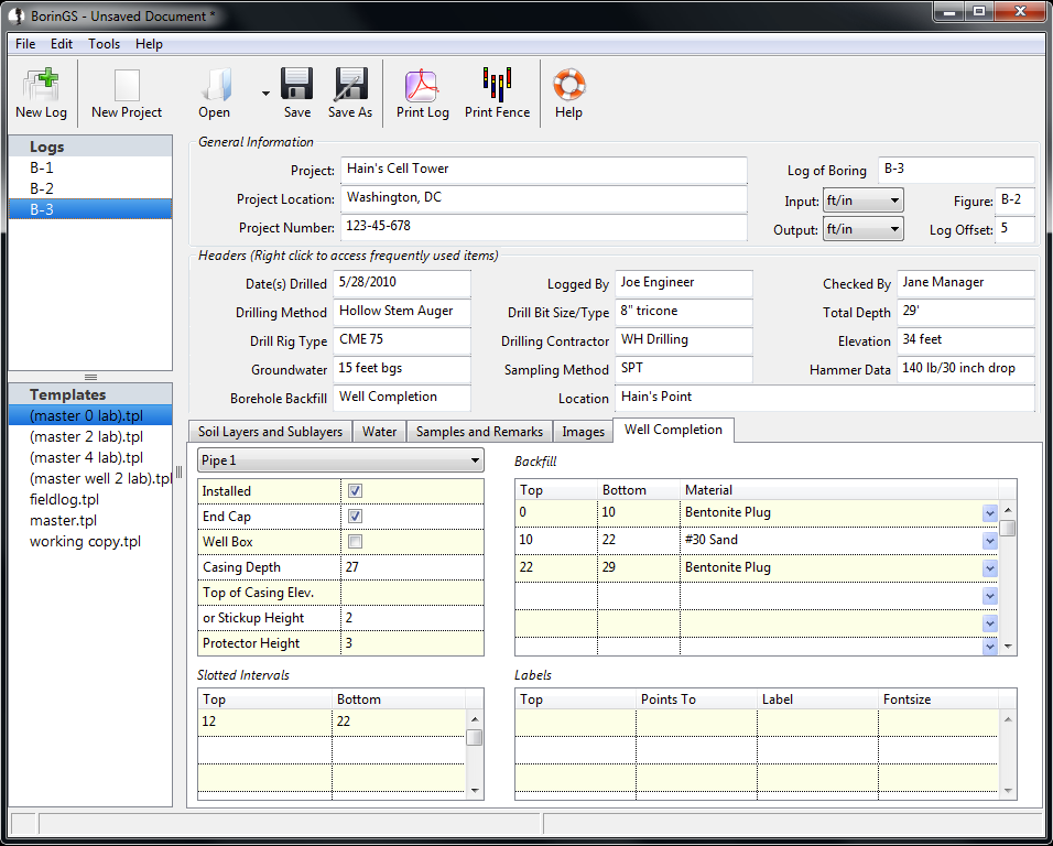
Up to five casings may be displayed on a log. Data for each
casing are entered by using the pulldown menu to select which casing is
being defined.
General
- Installed
- Check this box if the casing is installed.
- End Cap
- Check this box if an end cap should be drawn at the bottom of the
pipe on the log (draws as a solid line). If unchecked, the casing
will be drawn "open" at the bottom.
- Well Box
- When checked, a simple well box will be drawn above ground over
the top of the well.
- Casing Depth
- The depth to which casing was installed, entered in log units
below ground surface. This is required.
- Top of Casing Elevation or Stickup Height
- Only ONE of these values should be entered. If the
elevation of the top of casing is entered, it will be compared to the
surface elevation entered to determine the amount of stickup. If
the stickup height is entered, that amount of pipe will be drawn above
the surface on the log. If there is a stickup, the log may be
shifted down (see the General
Information section for more details on shifting the log).
- Protector Height
- If a protector was installed, enter the height here. As
with stickup, you may want to shift the log down.
Slotted Intervals
Define the slotted intervals in the casing here, based on depth
below
ground surface. Only the intervals within the "top" and "bottom"
entered will be drawn slotted. Multiple slotted intervals may be
defined.
Backfill
Enter the backfill used in this section. Note that the depths
are relative to the ground surface, and both the top and bottom are
required. Only defined material types are available. If an
undefined material is entered, that area will be blank when
printed. For
information on defining new material types, see the Editing Materials section.
Labels
These labels will be
printed in the "Remarks" column and may optionally point to a specific
part of the well log.
- Pipe 1-5
- Points to the center of the specified casing.
- Left Fill
- Points to the center of the fill on the leftmost side of the log.
- Center
- Points to the center of the well.
- Right Fill
- Points to the center of the fill on the rightmost side of the log.
- Right Edge
- Points to the right edge of the well column.
- Pipe 1-5 (side)
- Points to the right side of the specified casing.
- No Arrow
- No arrow will be drawn.